A Modern Take on Galileo's Thermometer and Goethe's Barometer
By Michael Parks, P.E., for Mouser Electronics
Most of us associate the name Galileo with astronomy. However, like many of his of Renaissance contemporaries,
Galileo Galilei had research interests that cut across a wide spectrum of scientific arenas. As part of his interest
in physics, he discovered a principle of liquids that demonstrated density changes in proportion with the liquids'
temperatures. This fundamental principle would be applied in a practical manner by Galileo's pupils in 1666 (two
years after Galileo's death).
The so-called Galileo thermometer, called the termometro lento (slow thermometer) in Italian, is
a wonderfully simple invention that arguably blends science and art in an elegantly visual way. The singular glass
tube is filled with a concentrated solution of ethanol and water. The density of the ethanol varies with temperature
changes more than water and as such causes a half-dozen or so colorful glass balls to float or sink. Interesting
fact: It is not the liquid within the colorful glass balls that affects their buoyancy. Rather, it is the metal tags
dangling underneath, which indicate to the user the ambient temperature, that adjust to alter the effective density
of each ball. As the ambient temperature decreases more balls float. Conversely, as the temperature increases more
balls sink.
Almost 70 years later, a German statesman by the name of Johann Wolfgang von Goethe would leverage his interest in
meteorology and work by the Italian physicist Evangelista Torricelli to invent the glass globe barometer.
(Fun fact: Torricelli was one of Galileo's pupils who invented the Galilean thermometer.) The glass globe or
Goethe barometer visually indicates the ambient atmospheric pressure by providing a mechanism with an
open-ended spout that is attached to an otherwise sealed glass vessel in which water can rise or fall. As the
atmospheric pressure rises, the water can push down the spout. As the pressure drops, the water can flow higher up
the spout, and typically, lower pressure indicates the approaching of nastier weather such as a thunderstorm.
While these inventions were groundbreaking achievements in their days, these devices are still readily available
for purchase from stores that offer scientific apparatuses (Figure 1). But here is a question: Can
we recreate both the Galileo thermometer and the Goethe barometer with a modern twist? Can we create something that
is both wonderfully intuitive yet whimsical for indicating ambient temperature and atmospheric pressure? That is the
challenge we will set out for ourselves.
Figure 1: The original Galileo thermometer (left) and Goethe barometer (right)
have a simple elegance about them.
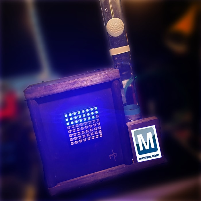
In this project, we will attempt to recreate and modernize the concept of these two inventions using the recently
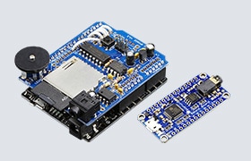
released MKR1010 development board. In addition, the Arm Cortex M0+ powered microcontroller in this project will
leverage the Bosch Sensortec BMP280 environmental sensor to collect barometric pressure and temperature data. To
convey this data to the user, we will incorporate a red, green, and blue (RGB) light-emitting diode (LED) matrix for
the temperature. For the pressure data, we will build a contraption that utilizes a blower fan, a lightweight ball,
and a glass tube. Lastly, we will transmit all data to the Medium One Internet of Things (IoT) platform via a
lightweight Message Queue Telemetry Transport (MQTT)-based messaging protocol.
Materials
Bill of Materials (BOM)
The BOM is listed below. Alternatively, you can visit mouser.com and grab all the parts you need from a prebuilt
shopping cart, just click
here. At the time of the writing of this project article, the BOM below is about $115 (in United States
dollars or USD). Table 1 lists the items in the BOM:
Table 1: Modern Galileo Thermometer Project BOM
Quantity
|
Mouser P/N
|
Description
|
Schematic P/N
|
|
1
|
782-ABX00023
|
Wi-Fi Development Tools (802.11) MKR WIFI 1010
|
MKR1010
|
|
1
|
485-1487
|
Adafruit Accessories NeoPixel NeoMatrix 8 X 8 64 RGB LED
|
LED Matrix
|
|
1
|
932-MIKROE-1097
|
Breadboard
|
|
|
1
|
854-ZW-MM-20
|
Male-to-Make Jumper Wires
|
|
|
1
|
485-2651
|
BMP280 Environmental Sensor
|
BMP280
|
|
1
|
603-CFR-25JR-52220R
|
Carbon Film Resistors 220ohm 1/4W 5%
|
R1
|
|
1
|
511-TIP122
|
Darlington Transistors NPN Power
|
T1
|
|
1
|
821-1N4001G-KR0G
|
Rectifiers Diode, 1A, 50V
|
D1
|
|
1
|
108-BFB0305HA-C
|
5VDC Blower Fan
|
M1
|
|
1
|
490-SWI10-5-N-MUB
|
Wall Mount AC Adapters 10W 5V 2A US, micro-USB
|
J1
|
|
1
|
349-M1IOTPROTO
|
Medium One IoT Prototyping Sandbox Subscription
|
|
Resources
All source files for this project are located on Mouser's GitHub repository.
Hardware Source Files
An EAGLE computer-aided design (CAD) schematic and circuit-board file reside in this folder for those who wish to
remix the project to suit their individual needs. For makers, a free version of EAGLE CAD is easily downloadable.
Software
The MKR1010 is programmable using the Arduino IDE. In addition to your use of the pre-built libraries that the
parts vendors offer, we will need to create two custom files. The first is a firmware file that will run on the
MKR1010 itself. We will write the firmware in Wiring, which is a wrapper for the C programming language tailored for
Arduino development boards. In addition, we will create a header (.h) file to store any sensitive data, such as
passwords and application programming interface (API) keys, which are things one should avoid sharing with the
entire world on GitHub. Both the firmware file (.ino) and the header file are in the software folder.
3D Printer Files
Our design is adapted for interfacing a laptop blower fan with a medical device for our purposes. The source .STL
file is included here. This allows the blower fan to mate into a cardboard lid that attaches to one end of the
plastic tube. (Note: If you don't have access to a 3D printer, simply using a piece of cardboard cut into a form
that fits into the tube as well as hugs the outside of the blower-fan outlet will be sufficient. Just be sure to use
contact adhesive to ensure a good seal.)
Images
Any visual image or screen captures of the schematic and 3D printer files will be stored in this folder for those
who don't have access or a need to view the original source files.
Tools
Here is a list of recommended tools to have on hand in order to complete this project:
- A Wi-Fi network
- Wire strippers
- Digital multimeter
- Needle nose pliers
- Hot-glue gun
- Soldering iron
- 60/40 solder
- Drill with 1/4" and 5/64" bits
- Contact adhesive
- Cardboard and/or 3D-printed part
Overview
The original Galileo thermometer and Goethe barometer have a simple elegance about them. This simplicity of design
made their use by laymen a trivial matter. Temperature and pressure data were conveyed using a very simple user
interface, albeit a mechanical one. This project will attempt to honor that legacy.
In this project, to convey the temperature, we will use an 8 X 8 RGB LED matrix. This matrix offers 64 data points,
which is probably not enough for the Fahrenheit scale. Therefore, let's use Celsius instead. 0°C to 64°C
translates to a range in Fahrenheit of 32°F (the freezing point of water) to approximately 147°F. Of course
if you prefer more resolution, a larger LED matrix can serve as a substitute in the design. Each pixel will
represent 1°C. In addition, if the current temperature reading is higher than the previous reading, then the
LEDs will glow red. If however the current temperature reading is lower, then the LEDs will glow blue, indicating a
falling temperature.
For the pressure reading, we will levitate a small plastic ball in a clear tube. The height of the ball will
represent the atmospheric pressure that the BMP280 environmental sensor will monitor. As a reference, the lowest
non-tornadic atmospheric pressure ever measured was 86.996 kilopascals (kPa), set in October 1979 during
Typhoon Tip. Also, the highest adjusted-to-sea level barometric pressure ever recorded (below 750 meters) was
108.381kPa, which occurred in Agata, Russia, in December 1968. These records give us a range of 86 to 109kPa, which
we can reasonably assume will encapsulate any pressure reading our project will ever see. We will use the
map()function from the Wiring language to map this range to a related voltage range that the pulse-width modulation
(PWM) pin will deliver to the blower fan. Lower voltages will result in the blower spinning slower (in fewer
revolutions per minute (RPM)) with the ball sinking to lower positions in the tube. Keep in mind that based on
experimentation, a 3.8 to 5V range seems sufficient. You should experiment with your setup and adjust the
FANLOWSPEED and FANHIGHSPEED constants accordingly. Currently FANHIGHSPEED is
set at 255, which represents a 100 percent PWM duty cycle [(255/255) * 5V = 5V]. FANLOWSPEED is set at
193 [(193/255) * 5V = 3.78V].
Building the Electronics
In this write-up, we are going to focus on using a breadboard (Figure 3). A good engineering
practice dictates that you should first test the circuit on a breadboard before moving on to more permanent
solutions such as a perfboard or printed circuit board (PCB). Here is a schematic (Figure 2) and
picture of the breadboard (Figure 3) to reference:
Figure 2: This diagram provides a schematic capture of the circuit. Notice the
use of screw terminals to connect wires from the blower fan and LED matrix board. This schematic is useful for a
permanent installation on a circuit board.
Figure 3: The electronic components for this project are mounted on a
breadboard to test the circuit.
MKR1010
- Place the MKR1010 towards the edge of the breadboard. From a mechanical perspective, it is better to place the
MKR1010 where its USB port barely hangs off the edge of the breadboard. Such placement will sacrifice a few
columns of contacts, but it will lessen the likelihood that the MKR1010 will catch on something and rip out of the
breadboard.
- Place a wire from the 3V pin to the power rail of the breadboard.
- Place a wire from the ground pin to the ground rail of the breadboard.
BMP280 Environmental Sensor
- Position the BMP280 breakout board closer to the MKR1010, but give yourself a few columns of contacts in between
the two boards. This will give you some wiggle room if you need to make alterations to the circuit during the
prototyping phase.
- Connect the SDA pin of the BMP280 board to the SDA pin of the MKR1010 with a jumper wire.
- Connect the SCL pin of the BMP280 board to the SCL pin of the MKR1010 with a jumper wire.
- Verify that the BMP280 breakout board that you select has pullup resistors onboard. If not, place a 10kΩ
resistor between the BMP280 SDA pin and the power rail. Place another 10kΩ resistor between the BMP280 SCL
pin and the power rail.
- Connect a jumper wire between the ground rail and the ground pin of the BMP280 board.
- Connect a jumper wire between the power rail and the Vin pin of the BMP280 board.
RGB NeoPixel LED Matrix
- Solder a female, 3-pin, right-angle header to the input pins on the back of the NeoMatrix board.
- Place a wire between the power rail and the Vin pin of the NeoMatrix board.
- Place a wire between the ground rail and the ground pin of the NeoMatrix board.
- Place a wire between the MKR1010's D6 pin and the digital in pin of the NeoMatrix board.
Blower Fan
- Place the TIP122 Darlington Pair transistor on the breadboard.
- Verify on the data sheet which pins are the base, collector, and emitter. Do NOT assume they are in order from
left to right.
- Place a 1N4001 diode between the collector and emitter of the TIP122.
- Place a 220ohm resistor between the MKR1010's D6 pin and the base of the TIP122.
- Connect a wire from the emitter of the TIP122 to the ground rail.
- Connect the negative lead of the blower fan to the collector pin of the TIP122.
- Connect the positive lead of the blower fan to the 5V pin on the MKR1010.
Software
In this section, we will detail the software side of the project. This will include the necessary firmware and
support files for the MKR1010 as well as the setup of the Medium One Sandbox in your web browser.
Figure 4: These serial debug messages are the first step to ensure MKR1010 is
talking to the BMP280 environmental sensor.
MKR1010 Firmware
Key Files
ino: The project-specific code for this effort is stored in this file. In this file, Medium One
provides an example to demonstrate how embedded devices can interact with the IoT-platform back end.h: When working on a project that is made publicly available, there is always a risk of exposing
sensitive data such as passwords or API keys. Instead of feeling the need to hardcode such information directly
into the firmware and having to remember to alter the code prior to each Git commit, we can instead create an
unpublished header file to store this information. Be sure to notice the example of a header file in the GitHub
repository. This example is named mysecretstuff.h. Remember to rename the file to secretstuff.h before attempting
to compile the code on your computer.
Key Libraries
The preprocessor directive #include lets us add libraries in our projects. These libraries promote code reuse.
Unless you have very specific needs, reinventing the wheel is not necessary. This project uses the following
libraries:
<PubSubClient.h>: This library enables the use of Medium One's MQTT communications API. It
handles a lot of the messy details for using the protocol by reducing our interaction using a series of function
calls.<Adafruit_NeoPixel.h>: The RGB LED matrix in use in this project is based on a popular LED
platform called NeoPixels. NeoPixels provide all the necessary hardware to make interfacing with WS2812B
or SK6812-based LEDs a simple matter of function calls.<WiFiNINA.h>: MKR1010 boards now have Wi-Fi to make interactions with web services within the
cloud straightforward. This library contains all the necessary code for the Arm M0+ processor to interact with the
Wi-Fi chipset. This code will allow us to create a Web client (Transmission Control Protocol/Internet Protocol
(TCP/IP) layer) that in turn can use the MQTT protocol to interact with Medium One's IoT Web service (an
application layer). It is important to note that this is a different library than the one used with the older
MKR1000 (which uses the h library).<Wire.h>: Interacting with the BMP280 environment sensor occurs over the inter-integrated
circuit (I2C) serial communications protocol. The h library provides the necessary foundational code to
interact with the I2C hardware. Component specific libraries will build upon this library to provide
functionality for their respective parts.<SPI.h>: Communication between the Arm Cortex M0+ microcontroller and the Wi-Fi chipset
occurs over a Serial Peripheral Interface (SPI) bus. This library provides the foundational code for that
interaction.<Adafruit_BMP085.h>: The BMP280 environmental sensor talks to the Arm Cortex M0+
microcontroller via I2 This library makes interacting with the BMP280 a matter of simply invoking a few
function calls to query data such as temperature and pressure."secretstuff.h": This header file contains sensitive information such as Wi-Fi passwords and the
Medium One passwords and API keys. Notice that this header file is encapsulated by quotation marks and not by <
or > (which the other header files utilize). This is because the h header file resides in our project specific
firmware folder and not the library of header files that all projects can use. Consequently, this header file is
only accessible to this project's firmware.
Key Variables and Constants
These are variables you might want to tweak depending on your design choices:
const int LEDPIN = 6: The pin to communicate with the NeoPixel matrix will be pin D6 on the
MKR1010.const int FANPIN = 7: The PWM pin used to control the fan speed will be pin D7.const int NUMPIXELS = 64: The number of individual NeoPixels in the NeoMatrix we will use is 64.
Adjust this number if you will use a matrix with a different number of pixels.const int DELAYAMOUNT = 500: The delay constant between each run of the main loop will be 500.const int REDCOLOR = 25: The brightness of LEDs when they are set to the color red is 25.const int BLUECOLOR = 25: The brightness of LEDs when they are set to the color blue is 25.const int LOWPRESSURE = 85: The lowest pressure reading we think we will see is 85kPa.const int HIGHPRESSURE = 110: The highest pressure reading we think we will see is 110kPa.const int FANLOWSPEED = 193: The PWM duty cycle to keep the Ping-Pong ball at its lowest set
position is 193.const int FANHIGHSPEED = 255: The PWM duty cycle to keep the Ping-Pong ball at its highest set
position is 255.
A quick note on the const keyword. Placing this keyword in front of the variable type ensures that this value will
not change during execution, in effect creating a constant instead of a variable. The advantage of const versus
#define is this: Because the variable has a type, the compiler ensures that the variable type is respected
throughout the code.
static int heartbeat_timer = 0: The heartbeat timer determines when to send a heartbeat message to
Medium One to inform the service that our device is still online.static int sensor_timer = 0: The sensor timer controls how often the BMP280 environmental sensor is
polled.static int heartbeat_period = 60000: The heartbeat period establishes the periodicity in which a
heartbeat message should occur. In this case, a message transmission will occur every minute.static int sensor_period = 5000: The sensor period sets the time between sensor readings to every
five seconds.long lastReconnectAttempt = 0: The last reconnect attempt tracks when the last time the device
attempted to connect to the Medium One service.static float prevTempC = 0.0: The float previous temperature tracks the previous temperature
reading so that we can toggle the color of the LEDs, depending on whether the temperature is getting warmer or
colder.
A note on the static keyword: The static keyword ensures that the value stored in the variable remains the same
(unless the code specifically changes), even when a function call goes out of scope. When the function is called
again later, the value that was held previously in the static variable will still be there to avoid the need to
declare and initiate the variable again as though it were the first time the function is called.
WiFiClient wifiClient: This command provides an object that allows our code to interact with the
onboard Wi-Fi chipset.Adafruit_BMP085 bmp: This command gives the firmware an object with which it can interact and poll
the BMP280 environmental sensor.Adafruit_NeoPixel pixels = Adafruit_NeoPixel(NUMPIXELS, LEDPIN, NEO_GRB + NEO_KHZ800): This command
provides an object that permits interfacing with the NeoPixel matrix.PubSubClient client(server, port, callback, wifiClient): This command establishes the MQTT
connection to Medium One and thus allows our code to interact with the web service via simple function calls.
Key Functions
void setup(): This first function will initialize many of the required hardware and software
components, such as the serial communications, Wi-Fi connection, sensor interface, and general-purpose
input/output (GPIO) pin interactions.void loop(): The loop function is the core of the functionality that will run continuously. It
ensures that the main loop has minimal code and that specific functionalities transfer to specialized functions in
which each are responsible for individual tasks essential to make the project work.boolean connectMQTT(): This function connects the MKR1010 to the Medium One MQTT server.void bmp_loop(): The BMP loop polls the BMP280 environmental sensor for temperature and pressure
data and transmits this data to Medium One.void heartbeat_loop(): This loop provides a heartbeat to the Medium One server. A heartbeat is a
consistently repeating packet that tells the server that our device is still alive and able to communicate, even
if there is no data to pass. This is very useful for applications that only transmit data when an event occurs in
the real-world.void displayResults(float tempC, float pressureKPA): The display results function takes the
temperature and pressure data and manipulates the LED matrix and blower fan RPMs in response to the environmental
data.
Setting Up Medium One
Figure 5: The Medium One Sandbox. Notice the data coming into the dashboard in
the center. Passwords and API keys are accessible from the left-hand navigation bar.
Medium One offers IoT developers a platform in which their IoT devices can communicate and compile data sets from
multiple IoT devices (Figure 5). The organization provides an excellent tutorial on activating
their service, click here to learn more about Medium One.
For this project's purposes, let's focus on the gotchas that are possible when setting up the MKR1010 to
communicate with Medium One via their MQTT API. We will leverage Medium One's MQTT protocol.
MQTT is a publish/subscribe-based messaging protocol. It sits atop the TCP/IP protocol. MQTT, unlike
Representational State Transfer (RESTful) APIs, requires a centralized message broker. Thus, endpoint
devices cannot directly communicate with each other, which has pros and cons. Whereas RESTful APIs rely on the
client to always initiate communications, MQTT allows a server to push data, thanks to the publish/subscribe
(Pub/Sub) architecture. RESTful devices can communicate with each other directly, but MQTT relies on a centralized
message broker (e.g., a server in the cloud).
Steps for Setup
Obviously the first step is to create an account at https://www.medium.one. Once you have an account, you will need to create a new project (click
the upper right corner of their web-based user interface to begin).
After the new project is activated, make a note of the crucial pieces of information that Medium One will
automatically generate for use in the firmware. You will store this information in the secretstuff.h
header file. The key pieces of information include:
Project ID: This alphanumeric string is a unique identifier assigned to this specific project. It
lets Medium One know what project to direct the MKR1010 environmental data to, especially if we have multiple
projects hosted with their web service.API Key: The API key is an auto-generated alphanumeric string that will allow us to log in and use
Medium One's API services.MQTT ID: Each project can have multiple contributors. The MQTT ID is an alphanumeric string that
Medium One generates. Important to note is that the Login ID is not the same as the MQTT ID. The Login ID is an
end-user created, human readable string (for example, "johndoe"). The piece of information we need for the
firmware is the MQTT ID and not the Login ID.User Password: Each user must create a user password when their account is established. For
security reasons, the password is not displayed, so be sure to remember this password!
Next, let's see where we can access these pieces of information from Medium One's website:
Setup -> Project Info: This command will display the Project ID.Setup -> Manage Users: This command is where the Login ID and the user's MQTT ID can be found.
Remember that it is the MQTT ID that is required for the firmware and not the Login ID.Setup -> Manage API Keys: This command leads to the API key.
Two other key pieces of information that the firmware will require is the Medium One MQTT server URL, which is ,
and the TCP port, which will either be 61619 (unsecure) or 61620 (secure). Lastly, we will need to setup a dashboard
to view if the data from the MKR1010 is being received. To do this, we will do the following:
- Go to the Dashboard and select the Single User Real Time Events Stream
- Select the user you wish to view from the dropdown box.
- This step should create the dashboard, which will start listening for data. If a green play button is
visible, click it to begin listening. Otherwise, there will be a red pause button that can be useful to
pause the feed if you desire.
- If it works, raw MQTT packets from the MKR1010 should begin displaying in the browser. Ensure that the MKR1010
is powered via a USB connection to a computer or alternating current (AC)-outlet wall wart power supply.
Assembly
If you decide to strictly follow this tutorial, then there are some things you must know to save yourself some
frustration while building this project as presented. Most of these suggestions involve the blower fan and getting
the Ping-Pong ball to float in response to the atmospheric pressure. Here are some things I did during my personal
experience with this project:
- I decided to use a 12" long, clear, polycarbonate, rigid tube with an interior diameter of 1-5/8" and a 1/16"
wall thickness. Next, I found some old 1½" in diameter Ping-Pong balls (from college I suspect). They fit
perfectly and allowed just enough space between the ball and the interior walls, so friction was not a concern.
- I drilled holes 1/4" deep up the tube at points where I wanted the ball to hover (Figure 6). I
chose five different spots, but you can tweak your own project as you desire. I drilled the topmost hole
approximately one ball in diameter just below the top of the polycarbonate tube.
- I placed a right seal between the blower's outlet port and the 3D-printed interface (Figure 7).
Also, I used a piece of cardboard to attach the interface onto the bottom of the polycarbonate tube. Then I
proceeded to use contact adhesive (such as the brand name adhesive Amazing Goop) to ensure all the parts were
sealed.
- I did not notice this next issue until everything was nearly finished. The Ping-Pong ball sat perfectly, too
perfectly, on the 3D-printed outlet adapter to the blower. This creates a seal that the blower has difficulty
overcoming even at a 100 percent duty cycle. My creative solution was to drill two (tiny) 5/64" holes at a point
just above the outlet and insert a toothpick (Figure 8). The toothpick prevents the Ping-Pong
ball from sitting nicely on the adapter outlet. My future iteration of the 3D-printed part will include an even
surface, so that the pull cannot create a seal.
- I chose to position the LED matrix, so that the LEDs fill from the top down, giving homage to a how Galileo's
thermometer counterintuitively works—that is, the more balls that float, the colder it is, and the fewer the
balls that float, the higher the temperature. However, if this method is not to your liking, simply install the
LED matrix upside down.

Figure 6: Use a 1/4" drill bit at a slow speed to drill vent holes along the
polycarbonate tube at the desired heights.
Figure 7: The 3D-printed part adapts the outlet of the blower to the
polycarbonate tube. Good seals between all components (including the blower, adapter, and tube) are critical.
Contact adhesive greatly helps to achieve this goal.
Figure 8: You may use a toothpick to prevent the plastic ball from setting on
the blower-fan adapter and creating a seal.
Project in Action
To initiate the final steps, connect to a computer if you want to serial debug messages (Figure
4). Open a serial terminal like Putty and find the MKR1010 as the COM port (or serial port). Ensure it is
set for a baud rate of 9600. Then login to your Medium One Sandbox and select the project dashboard. Be sure to
press the green arrow play button, and you will begin to see data from the MKR1010 populate in the browser.
The LEDs and blower fan should start to engage as well.
Now it is your turn to take this project and improve upon it. You might have noticed that we purposefully omitted
any mechanism that indicates that the atmospheric pressure is rising or falling over time. Remember that we did this
with the temperature, by changing the LEDs to blue if the temperature is falling or red if the temperature is
rising. Since there are plenty of GPIO pins left, use your imagination and let us know how you would tweak the
design to indicate whether the pressure is rising or falling.
We would love to hear feedback if you've attempted this project, improved it, or created something unique! Feel
free to drop us a message on Facebook, Twitter, LinkedIn, or Instagram.
 Michael Parks, P.E. is a contributing
writer for Mouser Electronics and the owner of Green Shoe Garage, a custom electronics design studio and technology
consultancy located in Southern Maryland. He produces the S.T.E.A.M. Power Podcast to help raise public awareness of
technical and scientific matters. Michael is also a licensed Professional Engineer in the state of Maryland and
holds a Master’s degree in systems engineering from Johns Hopkins University.
Michael Parks, P.E. is a contributing
writer for Mouser Electronics and the owner of Green Shoe Garage, a custom electronics design studio and technology
consultancy located in Southern Maryland. He produces the S.T.E.A.M. Power Podcast to help raise public awareness of
technical and scientific matters. Michael is also a licensed Professional Engineer in the state of Maryland and
holds a Master’s degree in systems engineering from Johns Hopkins University.