


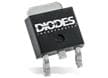
Diodes Incorporated 2N7002 N-Channel E-Mode Field Effect Transistors
Diodes Incorporated 2N7002 N-Channel Enhancement-Mode Field Effect Transistors (FETs) are designed for low-voltage switching applications. These 2N7002 devices feature a maximum drain-source voltage (VDS) of 60V, a continuous drain current (ID) ranging from 105mA to 210mA, and a low on-resistance [RDS(on)] ranging from 7.5Ω to 13.5Ω. The FETs offer fast switching performance with low gate charge, suitable for signal processing, load switching, and level-shifting applications. The Diodes Inc. transistors are housed in a compact SOT-23 package, ensuring space efficiency for high-density circuit designs. Additionally, 2N7002 FETs are lead-free, RoHS-compliant, and designed for automated surface-mount assembly.
Features
- Low on-resistance
- Low gate threshold voltage
- Low input capacitance
- Fast switching speed
- Small surface-mount SOT23 package
- Moisture Sensitivity Level (MSL) 1 per J-STD-020
- Totally lead-free and fully RoHS compliant
- Halogen-/antimony-free Green device
Applications
- Motor controls
- Power-management functions
Specifications
- 60V maximum drain-source/-gate voltage
- Maximum gate-source voltage
- ±20V continuous
- ±40V pulsed
- 105mA to 210mA maximum continuous steady state drain current range
- Maximum continuous body diode forward current
- 0.2A continuous
- 0.5A pulsed
- 800mA maximum pulsed drain current
- 370mW to 540mW total power dissipation
- Off characteristics
- 70V typical drain-source breakdown voltage
- 1.0µA (+25°C) to500µA (+125°C) zero gate voltage drain current range
- ±10nA maximum gate-body leakage
- On characteristics
- 1.0V to 2.5V gate threshold voltage range
- 7.5Ω to 13.5Ω maximum static drain-source on-resistance range
- 1.0A typical on-state drain current
- 80mS minimum forward transconductance
- 1.5V maximum diode forward voltage
- Dynamic characteristics
- 50pF maximum input capacitance, 22pF typical
- 25pF maximum output capacitance, 11pF typical
- 5.0pF maximum reverse transfer capacitance, 2.0pF typical
- 120Ω typical gate resistance
- 223pC typical total gate charge
- 82pC typical gate-source charge
- 178pC typical gate-drain charge
- 2.8ns typical turn-on delay time
- 3.0ns typical turn-on rise time
- 7.6ns typical turn-off delay time
- 5.6ns typical turn-off fall time
- Maximum thermal resistance
- 241°C/W to 348°C/W junction-to-ambient range
- 91°C/W junction-to-case
- -55°C to +150°C operating temperature range
- UL 94V-0 rated molded plastic, Green molding compound
- Matte tin-plated leads, solderable per MILSTD-202, Method 208
Related MOSFETs
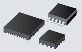
Diodes Incorporated Power MOSFETs
Portfolio of power MOSFETs with new N- and P-channel devices with breakdown voltages up to 6450V.
Đã phát hành: 2025-10-23
| Đã cập nhật: 2025-10-31